
This work is licensed under a Creative Commons Attribution 4.0 International License.
GRASSHOPPER GRID SPREADING
LOGIC
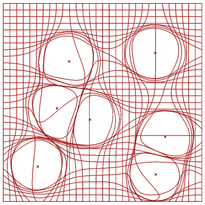
1. Create a grid
2. Measure distance between grid intersections and spread points
2. Split points into those within the radial distance and those outside
3. Move points inside to their closest point outside
4. Remove overlapping points that exist in the same x,y,z coordinates
5. Connect points to make new spread grid

GH Version
0.9.0065
Tip
The polyline component may turn yellow. This does not mean there is something
wrong it is just the component automatically collapsing zero length line segments.
This works with all curves in general so try custom grids. Use only one grid
axis for nice muscle like effects. Try then skinning the pathways with metaballs
and mesh from points or using millipede. To get perfect triangulation just stop at
the polyline component.


This work is licensed under a Creative Commons Attribution 4.0 International License.
Hi Michael,
ReplyDeleteTHanks for the script. I am, however having problems getting mine to work. In your script the bottom cull button, next to the "P" plug in has a square diagonally divided light and dark. I don't know what this is. How do I get it?
thanks!
Nevermind! I got it - Its the "invert" button.
ReplyDeleteis it possible to control every single point?
ReplyDeletethanks
Love your work, this is sooo awesome! Thank you very much for these great tutorials!
ReplyDeletehow do i make a one direction grid? [awesome ideas]
ReplyDeleteJust plug recgrid "P" directly into pline "V"
ReplyDeleteThanks for the tutorial, Michael - it's been really helpful. I'm trying to figure out how to make it so that the distorted grid lines don't intersect with nearby distorted lines running in the same axial direction. I turned off the merge and reverse nodes in the beginning and connected the grid directly to the initial poly line node to achieve a result similar to your last image. Have you found a way to manipulate this definition so that the distorted lines are a bit more controlled in their distortion?
ReplyDeleteWhen did you last attempt it? I updated the def and its a lot more accurate. My goal though is to provide basic "starter" definitions to which you can then add to. So of course you can get more accuracy depending your goal by using other tools such as graph mappers and varying spread values. In this definition if you make the section called "point density" very high the more accurate it will be.
ReplyDeleteThanks for this definition! I have it mostly working, but am having a little bit of trouble that I can't figure out the solution to: when I have gridlines that do not cross the radius of any of the spread points, they are disappearing. It seems to be happening at the Replace -- my list comes out with less values than it went in with, losing all of the points on the unaffected gridlines. Any suggestions for troubleshooting this?
ReplyDeleteI cant be sure without seeing it. As you can see from my images above I am not having this issue.
ReplyDeleteHello
ReplyDeleteIs it possible to apply this on 3D surface (right)? I was trying, but I have problems with "circles"...Their centres are on surface (marked yellow), but when I conect them, they are not in the same plane like surface...I think I need to apply them somehow on my surface but don't know how.
Hope You can help. :) Thanks
dm capture:
ReplyDeletehttps://fbcdn-sphotos-h-a.akamaihd.net/hphotos-ak-prn2/v/t35.0-12/1899844_268014056692880_1522679180_o.jpg?oh=5be11111f4c8e834058562d2697b18ff&oe=532CBF1A&__gda__=1395404204_be048b85a830afb8b54b73a839def139
gh:
https://fbcdn-sphotos-h-a.akamaihd.net/hphotos-ak-prn2/v/t35.0-12/1939549_268014373359515_884042252_o.jpg?oh=6907f078d4a033edb9388ff8ef64deed&oe=532C9E76&__gda__=1395429531_d788e9373d0a86c55422a5b140e07f7e
hello, it seems i cant find where to download the definition from!
ReplyDeleteI love your work but I cant seem to work it out on my computer. I think I might have a problem with the first CP component. everything from there on seems to turn yellow with warnings. It cant capture my data, do I need to refrence some specific points to the POINT component? I think my problem comes from trying to spread the points!
ReplyDeleteHey I did it and it worked! very nice exercise! But i ve been wondering if there was a way of turning those 2d blobs inside the grid into a 3d blob with the same lines! i tried pulling them up and lofting and other things but they didnt work! Please any kind of help would be great! Thank you very much!
ReplyDeletecan we think these lines are elevated at certain points ?
ReplyDeletehow can we achieve it with this definition ?
thxxx
ReplyDeleteplease can you put up a video tutorial of this please pretty please. i just do not under stand.
ReplyDeleteit doesnt seem to work. am i supposed to add to this definiton because I dont see my points interacting with the grid and they are linked
ReplyDeleteCan anyone share the script please?
ReplyDeletenews sports evry thingsنصائح لمرضى الجيوب الأنفية
ReplyDeleteرياضة
اسعار الذهب في اليمن
قنوات اون تايم سبورت
اخبار اليمن
تردد قنوات SSC
المشهد اليمني
just here in masdrksdfsdfsdfsdf